HFSS Analysis: Engineering Foundations and Industrial Applications of High-Frequency Electromagnetic Simulation
ANSYS HFSS (High Frequency Structure Simulator) is a full-wave 3D electromagnetic field simulation software designed to solve high-frequency electromagnetic problems in the frequency domain.
HFSS is widely accepted as an industry standard for:
- RF and microwave component design
- Antenna performance validation
- Radar and defense systems
- EMI/EMC investigations
- High-speed PCB and Signal Integrity (SI/PI) analysis
At high frequencies, lumped circuit approximations become invalid. Wave propagation, phase delay, coupling, resonance, and boundary effects dominate system behavior. Therefore, a full-wave solution of Maxwell’s equations becomes essential.
Electromagnetic Fundamentals: What Does HFSS Solve?
HFSS directly solves Maxwell’s equations in the frequency domain:
∇×E=−jωμH\nabla \times \mathbf{E} = -j\omega\mu \mathbf{H}∇×E=−jωμH ∇×H=J+jωεE\nabla \times \mathbf{H} = \mathbf{J} + j\omega\varepsilon \mathbf{E}∇×H=J+jωεE
The software applies:
- Vector Finite Element Method (FEM)
- Edge-based basis functions
- Adaptive mesh refinement
This methodology ensures:
- Accurate surface current calculation
- Proper dielectric boundary representation
- Precise resonance mode extraction
Solution Methodology: Finite Element Approach
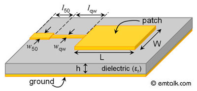
Step 1 – 3D Geometry Definition
Import or create detailed CAD geometry (antenna, waveguide, enclosure, PCB, etc.)
Step 2 – Material Assignment
- Relative permittivity (εr)
- Relative permeability (μr)
- Conductivity (σ)
- Loss tangent
Step 3 – Boundary Conditions
- Perfect Electric Conductor (PEC)
- Radiation boundary
- Perfectly Matched Layer (PML)
- Symmetry planes
Step 4 – Port Definition
- Wave ports
- Lumped ports
- Terminal ports
Step 5 – Adaptive Meshing

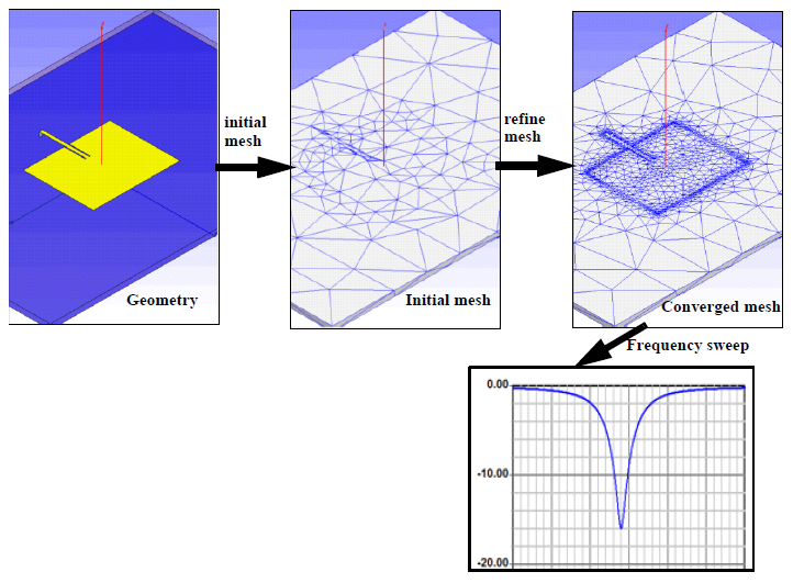
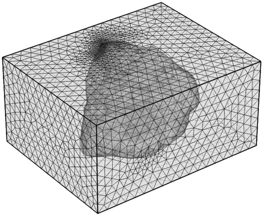
HFSS uses tetrahedral mesh elements. The adaptive mesh refinement algorithm:
- Refines regions with high field gradients
- Iteratively reduces solution error
- Continues until convergence criteria are met
This is especially critical for resonant structures and high-Q components.
Solution Types in HFSS
| Solution Type | Application |
|---|---|
| Driven Modal | S-parameter extraction |
| Driven Terminal | Multi-conductor structures |
| Eigenmode | Resonance frequency analysis |
| Transient | Time-domain behavior |
| SBR+ | Large-scale RCS problems |
Critical Analysis Applications
Antenna Analysis
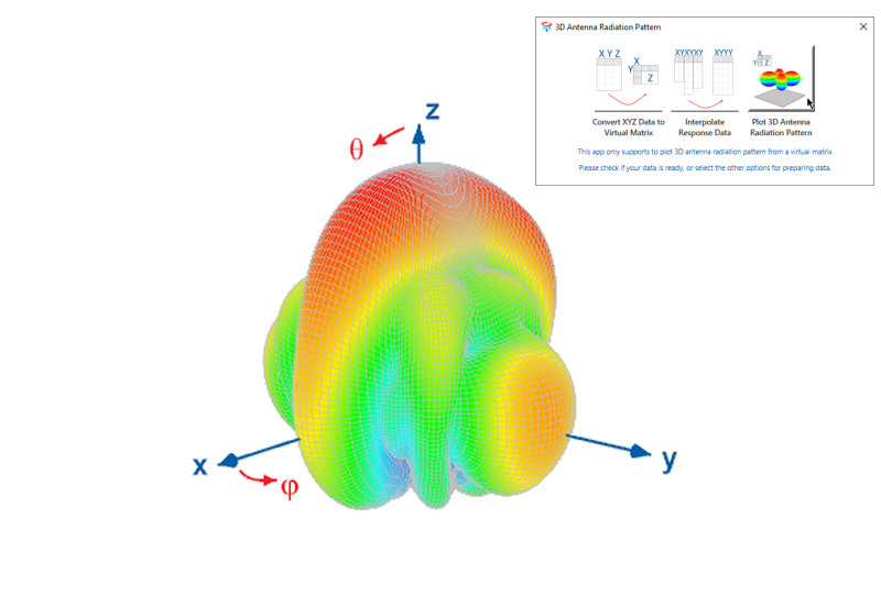
HFSS enables detailed antenna performance evaluation:
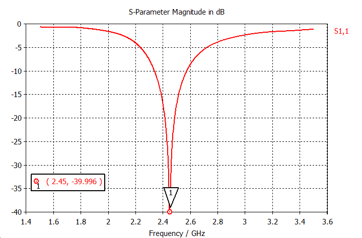
- Return Loss (S11)
- VSWR
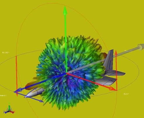
- Radiation pattern
- Gain and directivity
- Efficiency
- Polarization
A key antenna performance criterion:
S11<−10 dBS_{11} < -10 \text{ dB}S11<−10 dB
This indicates that more than 90% of the input power is delivered to the antenna.
RF & Microwave Components
HFSS is widely used for:
- Band-pass / low-pass filters
- Couplers
- Power dividers
- Waveguide structures
- Resonators
Above 10 GHz, full-wave solutions are mandatory due to higher-order mode propagation and complex field interactions.
Radar Cross Section (RCS) Analysis
4
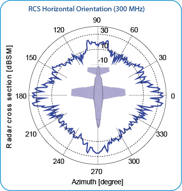
In defense applications, RCS analysis is critical.
The RCS is defined as:
σ=4πR2∣Es∣2∣Ei∣2\sigma = 4\pi R^2 \frac{|E_s|^2}{|E_i|^2}σ=4πR2∣Ei∣2∣Es∣2
HFSS SBR+ solver enables large-scale electromagnetic scattering simulations for aircraft, naval platforms, and complex geometries.
EMI / EMC Analysis
HFSS supports:
- Electromagnetic coupling studies
- PCB radiation analysis
- Shielding effectiveness evaluation
- Enclosure performance validation
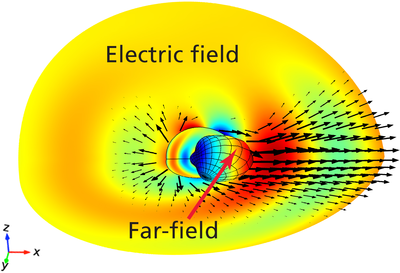
Both near-field and far-field quantities can be extracted for compliance assessment.
Signal Integrity (SI) and Power Integrity (PI)
Using HFSS 3D Layout:
- Crosstalk analysis
- Reflection and impedance mismatch detection
- Power plane resonance investigation
- Return path discontinuity analysis
This is essential for high-speed digital systems and RF-integrated electronics.
HFSS vs Low-Frequency Solvers
| Software | Frequency Range | Typical Use |
|---|---|---|
| ANSYS Maxwell | Low frequency | Motors, transformers |
| ANSYS HFSS | High frequency | RF, antennas |
| ANSYS SIwave | PCB-level | SI/PI analysis |
HFSS is specifically optimized for high-frequency wave phenomena.
Multi-Physics Engineering Approach at FE-TECH
FE-TECH combines electromagnetic simulations with:
- Structural analysis (ANSYS Mechanical)
- Impact & ballistic simulations (LS-DYNA)
- CFD analysis (Fluent)
- Fatigue evaluation (Endurica)
- Structural verification (SDC Verifier)
This enables:
✔ Antenna deformation impact → Structural + HFSS
✔ Radar enclosure mechanical influence → Coupled analysis
✔ EMI-induced performance degradation → Multi-physics validation
Such integrated methodology is especially critical in defense, aerospace, and automotive radar projects.
Computational Challenges in HFSS
- Large memory requirements
- High computational cost
- Mesh convergence sensitivity
- Boundary condition misinterpretation risks
- Long solution times for electrically large models
Therefore, experienced electromagnetic engineering expertise is essential for reliable results.
HFSS analysis enables:
- Prototype cost reduction
- Accelerated design validation
- Early EMI risk detection
- Reliable performance prediction in defense and telecommunications systems
At FE-TECH Advanced Engineering, we provide comprehensive high-frequency electromagnetic simulation services including design validation, optimization, and technical reporting for mission-critical applications.