Generative Topology Optimization of Pump Housings in Ansys Discovery Software
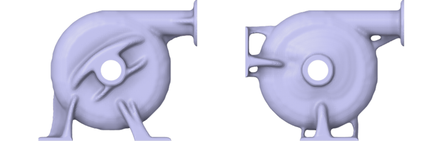
Topology optimization is not only a lightweighting exercise. When combined with realistic loading, support variations, manufacturing controls, reverse engineering, and validation, it becomes a practical workflow for creating structurally efficient, manufacturable components.
Topology optimization helps engineering teams move beyond incremental material removal and toward simulation-driven structural innovation. In this workflow, Ansys Discovery 3D product simulation software is used to explore generative topology optimization for a pump housing application, starting from a simplified design space around the volute region. The objective is to identify efficient structural load paths while reducing unnecessary material, maintaining structural performance, and accounting for manufacturability.
Using internal pressure loading, fixed support conditions, optimization goals, and manufacturing constraints, the workflow demonstrates how different support locations and constraint strategies can drive different optimized support structures. The resulting topology output can then be reverse-engineered into clean computer-aided design (CAD) geometry and validated through structural simulation before moving toward final design.
Why Topology Optimization Matters
Many traditional structural components are designed conservatively. They often include extra material to ensure stiffness, durability, and manufacturability, but this can lead to unnecessary mass, higher material cost, and increased carbon impact. For pump housings and similar industrial components, the challenge is not simply to remove material. The goal is to create a design that is lighter, structurally efficient, manufacturable, and validated against realistic operating conditions.
Topology optimization provides a physics-driven method for identifying where material is truly needed. Rather than beginning with a finished CAD design and manually removing material, engineers can begin with a larger allowable design space and let the optimizer evolve the structure based on loads, supports, objectives, and constraints.
In the pump housing example, the workflow begins with a lumped body around the volute region and uses Discovery software to generate optimized support structures based on different objectives and final assembly constraint variations.
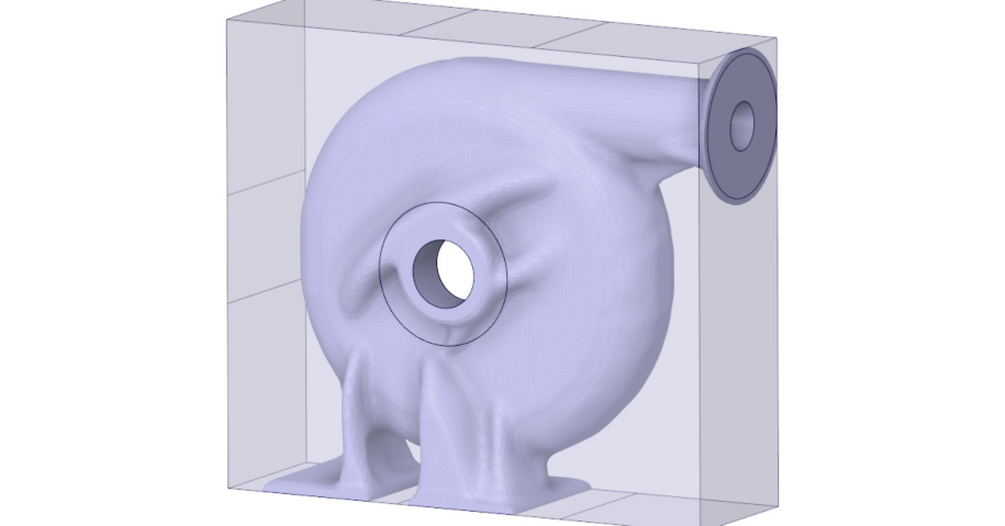
Lumped body/design space
The Engineering Challenge
Pump housings can be exposed to internal pressure loads, mounting constraints, assembly requirements, and durability expectations. The housing must remain structurally robust while fitting into the final assembly envelope. At the same time, design teams may want to reduce material usage, improve the performance-to-weight ratio, and avoid overbuilt support structures.
- Where does the housing actually need material to carry the load?
- How do different mounting locations change the optimized support paths?
- Can the design be made lighter without sacrificing stiffness or stress performance?
- Can manufacturing constraints guide the optimizer toward practical shapes?
- How can the organic topology result be converted back into clean CAD geometry?
The Simulation-Driven Workflow in Discovery Software
The workflow starts by defining the design space around the pump housing. Instead of only modifying the original geometry, the engineer creates a volume region around the volute. This gives the optimizer space to generate new support structures while preserving key interfaces.
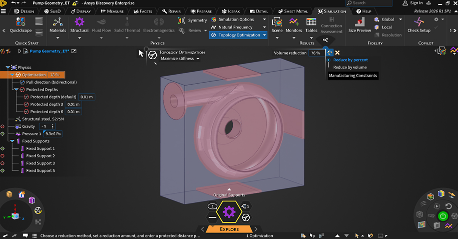
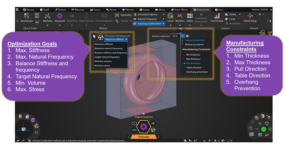
A topology optimization setup with design goals, volume reduction, protected regions, and manufacturing constraints
1. Define the starting design space.
The starting point includes a design space around the volute, preserved interfaces for critical connection areas, structural steel as the baseline material, internal pressure applied to the volute region, and fixed supports applied at selected mounting or assembly locations.
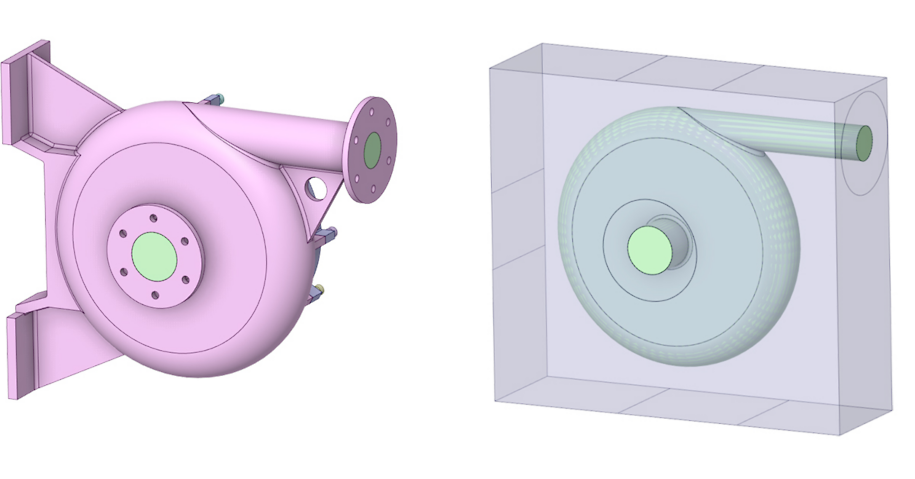
The starting point: design space around the volute and preserved functional interfaces
Define the available design space using a surrounding volume region.
- Preserve the pump housing key connection interfaces.
- Optimize the housing shape in the allowable envelope.
- Assign structural steel as the baseline material.
2. Apply physics conditions.
The structural setup includes realistic boundary conditions, such as internal pressure and fixed supports. These conditions are critical because topology optimization is load path-driven. If the support locations change, the optimized structure changes as well.
This is especially important for final assembly studies. A support at the bottom, rear, side, or top can produce different structural paths. By varying the support assumptions, engineers can understand how the final assembly configuration affects the optimized geometry.
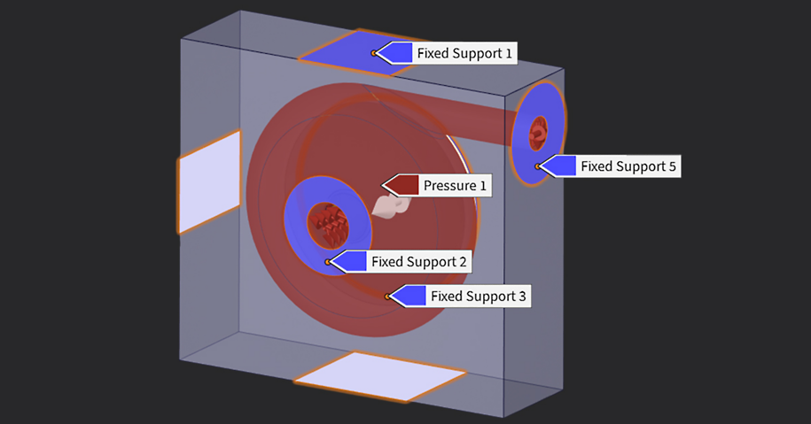
The physics setup: apply loads, constraints, etc.
3. Select optimization goals.
Discovery software provides topology optimization goals that enable the engineer to steer the design based on the desired structural behavior. For the pump housing workflow, a balanced stiffness and frequency objective is useful because the housing should remain structurally robust while avoiding undesirable dynamic behavior.
| Optimization goal | Purpose in structural design exploration |
| Maximize stiffness | Reduce compliance and create a stiffer structure for the remaining material. |
| Maximize natural frequency | Improve vibration behavior and reduce the likelihood of resonance. |
| Balance stiffness and frequency | Combine static stiffness and dynamic response considerations. |
| Target natural frequency | Drive the structure toward a specified frequency target. |
| Minimize volume | Remove material based on stress, safety factor, or aggressiveness targets. |
| Minimize stress | Reduce stress concentration and improve durability. |
4. Add manufacturing constraints.
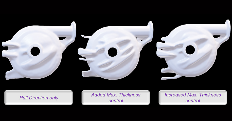
Manufacturing constraints help prevent the optimizer from producing shapes that are theoretically efficient but difficult or impractical to manufacture. In Discovery software, constraints like minimum thickness, maximum thickness, pull direction, table direction, and overhang prevention can guide the final shape.
| Manufacturing constraint | How it guides the optimized geometry |
| Minimum thickness | Controls the minimum feature size; useful for avoiding fragile or unmanufacturable thin members |
| Maximum thickness | Limits overly bulky regions; useful when wall thickness control matters for casting or molding |
| Pull direction | Supports mold-based manufacturing by specifying the removal direction from the mold |
| Table direction | Guides geometry for 2.5-axis milling by specifying the part orientation for machining |
| Overhang prevention | Supports additive manufacturing by reducing unsupported overhangs during 3D printing |
An Application Example: Pump Housing Optimization
In this pump housing case study, the goal is to generate efficient support structures around the pump volute while maintaining the functional interfaces required for final assembly.
The workflow evaluates design variations: original support locations, different support locations, and open-ended support regions where the optimizer is allowed more freedom to identify efficient support paths.
Original support location
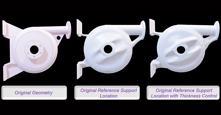
The first setup uses predefined support locations based on the original or reference assembly. This provides a baseline for understanding how the optimizer reinforces the housing when the support strategy is already known.
Different support locations
Next, the support locations are varied. For example, the model can be evaluated with support at the bottom, support at the bottom and rear, or support at the bottom, rear, and top. Each configuration changes the available load paths. As a result, the optimizer generates different support structures depending on how the pump housing is constrained in the final assembly.
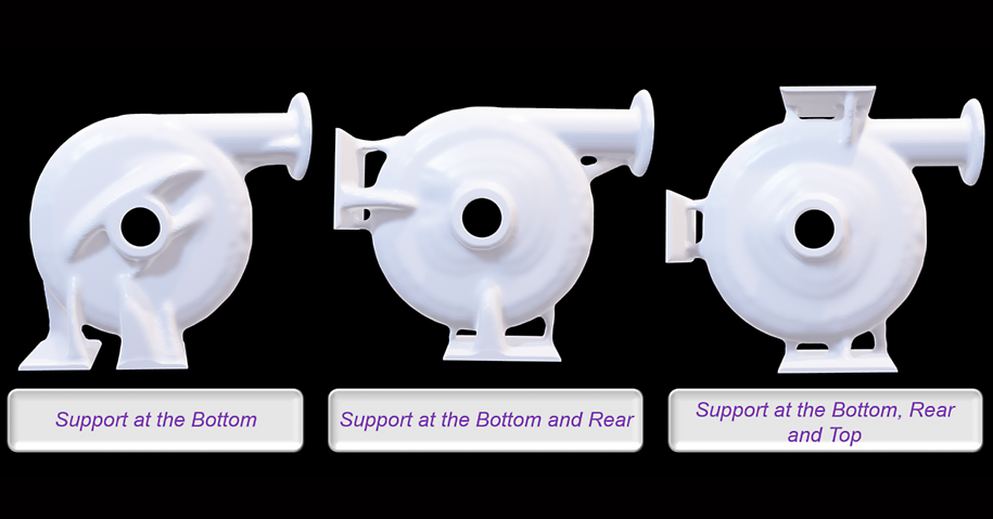
Final assembly constraint variation: Mounting location assumptions drive different optimized support structures.
No predefined support location
In another workflow, the optimizer is given more freedom by permitting support structures to form across broader regions, such as the bottom, rear, or top. This helps answer a more open-ended design question: If the final support structure is not fixed, where should the material go?
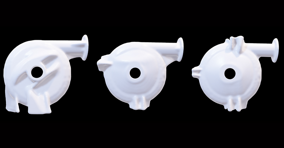
Performance and Sustainability Benefits
Topology optimization supports both performance and sustainability goals. By removing unnecessary material and reinforcing only where the load path requires it, engineers can improve the performance-to-weight ratio while reducing waste.
Performance and sustainability: Reduce material waste while maintaining structural performance.
Reduce material usage while maintaining structural performance.
- Minimize unnecessary mass in low-stress regions.
- Improve the performance-to-weight ratio.
- Lower material waste and potential manufacturing cost.
- Support lower-impact designs through optimized geometry.
The lightest design is not automatically the best design. The optimized result must still satisfy stress, stiffness, frequency, manufacturability, and assembly requirements. The value comes from using simulation to understand those trade-offs earlier in the design cycle.
Reverse Engineering: Turning Topology Output Into CAD
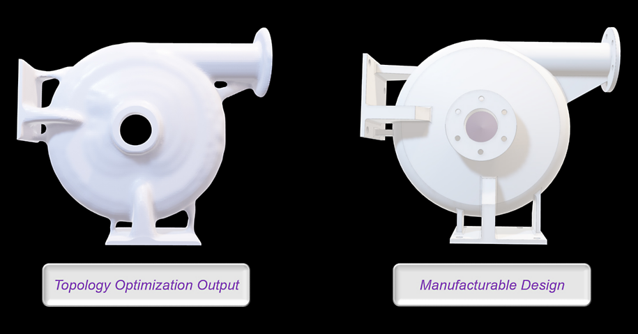
Topology optimization results are often organic. They show where material should exist, but they are not always ready for manufacturing as is. After the optimization run, the next step is to convert the optimized shape into clean, editable CAD geometry.
- Reconstruct smooth surfaces from the topology result.
- Preserve functional interfaces and mounting regions.
- Convert organic members into manufacturable ribs, walls, or welded structures.
- Simplify geometry where needed for downstream CAD, simulation, or manufacturing.
- Prepare the geometry for validation simulation.
This closes the loop between simulation-driven ideation and practical engineering design. The topology output becomes a guide for a manufacturable CAD model rather than the final production geometry by itself.
Validation: Confirming the Final Design
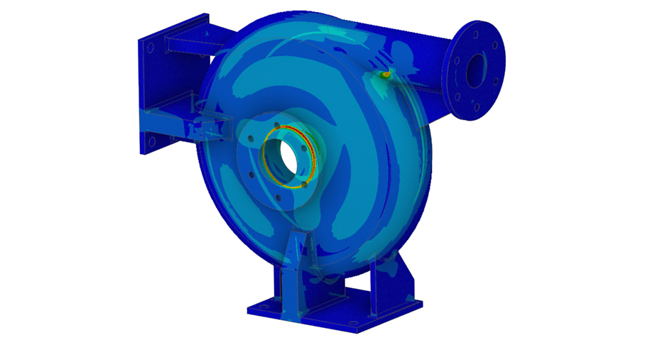
After reverse engineering, the final CAD design should be validated under realistic operating conditions. This step is essential because the topology result is an optimized concept, not the final proof of performance.
- Apply the same pressure loads and support conditions used during optimization.
- Check Von Mises stress against material limits.
- Compare the optimized design against the original baseline geometry.
- Review deformation and stiffness behavior.
- Verify that stress concentrations were not introduced during CAD reconstruction.
- Confirm that the final design remains manufacturable and assembly-ready.
Best Practices for Structural Topology Optimization
To get meaningful topology optimization results, the setup must be intentional. The optimizer can only respond to the design space, loads, constraints, and goals that are provided.
Define the design space carefully: The design space should be large enough to enable meaningful material redistribution but not so broad that the optimizer creates unrealistic support structures.
Preserve critical interfaces: Bolt holes, flange faces, inlet/outlet regions, bearing surfaces, sealing surfaces, and assembly interfaces should be protected so the optimized result remains functional.
Use realistic loads and supports: Topology optimization is highly sensitive to boundary conditions. Unrealistic support assumptions can produce designs that look efficient but fail to represent the real assembly.
Compare multiple constraint scenarios: Different mounting locations can create different optimized support paths. Running multiple constraint variations helps teams understand the design envelope and select the most robust option.
Include manufacturing constraints early: Minimum thickness, maximum thickness, pull direction, table direction, and overhang prevention should be used early so the optimized result is closer to a manufacturable design.
Always validate the reconstructed CAD: The final CAD geometry should be re-simulated after reverse engineering. The validation model is the final check before design release or detailed analysis.
Simulation-Driven Structural Design
Topology optimization in Discovery software enables engineers to move from conventional material removal to simulation-driven structural design. For pump housings and similar industrial components, the workflow can help identify efficient load paths, reduce unnecessary material, and explore how different mounting locations affect the final structure.
The key value is not simply lightweighting. The value is giving engineers a faster way to explore structural design alternatives, apply manufacturability rules, generate performance-driven concepts, and validate those concepts before committing to detailed design or manufacturing.
By combining topology optimization, manufacturing constraints, reverse engineering, and validation, engineering teams can create designs that are lighter, more efficient, and better aligned with real assembly requirements.